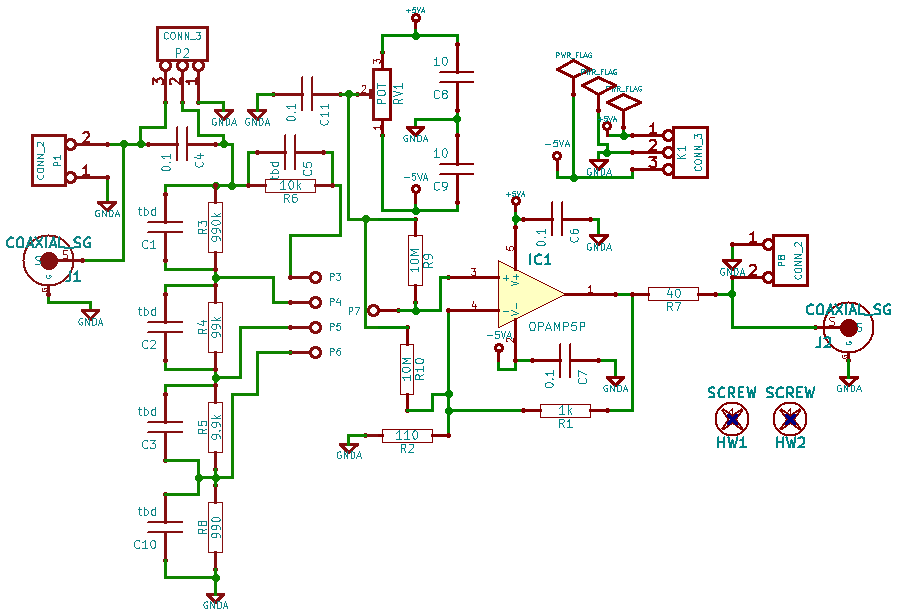
This is a simple preamp using the Analog Devices AD8067 IC, which is an opamp-like device with a rated bandwidth of 54 MHz at a gain of 10. It has a high-impedance FET input and the output can drive a 50-ohm load. I'm experimenting with it as a high-impedance range-switched front-end amplifier for the MHZ100Q boards. This is the first try at a pcb, so it's a work in progress.

For compactness and cost, it uses 0.1 inch jumpers instead of switches. The R3,R4,R5,R8 resistor
ladder forms an input attenuator with 10x steps and 1 Meg input resistance. A jumper from tie point
P7 to one of P3-P6 selects the desired input attenuation.
Jumper P2 is equivalent to the AC/DC/Gnd input switch on many scopes. With no jumper, the input is AC-coupled. With a jumper on pins 2 and 3, it's DC-coupled. With a jumper on pins 1 and 2, the input to the divider chain is grounded.
Pot RV1 and resistors R9 or R10 are for experimenting with adding a DC-offset to the signal. All 3 are being left off until I get a chance to see how well they work.
Inputs and outputs are designed for an SMA connector to be mounted sideways on the pcb. Room for two-pin header for input and output are also provided if one can get by without coax interconnecting cables.
Input power is +5 and -5 volts, connected to the K1 connector.
Blank PCB's are available from Oshpark. See the link on the widgets page.
Comments and questions can be posted to my blog at blog.sensicomm.com/2014/03/widgets.html
I'll update this page when I get boards assembled and working.