This page describes the MHZ100Q2 pcb and associated firmware.

Schematics are here: mhz100q_schematic.pdf
The MHZ100Q2 connects to a standard USB port, and draws its power from the USB bus. If using a USB hub, you probably need a hub with an external power supply so that it can supply the full 500ma that USB is supposed to provide.
Software access is via the libusb library, so no USB driver
needs to be installed. Version 1.0 of libusb is used. In Debian you can install it using:
apt-get install libusb-1.0-0-dev
to get the proper version.
Note that apt-get install libusb-dev pulls in the 0.1 version instead. Version
0.1 is unnecessary for this software, but having it installed in addition to 1.0 is not a problem.
Assuming your Linux install uses the udev package to support pluggable devices, you need to create a file
/etc/udev/rules.d/03mhz100q2.rules
with contents
# My assigned numbers for the basic opencores usb1_funct implementation.


ATTRS{idVendor}=="00fe" ATTRS{idProduct}=="2100" MODE="666" GROUP="plugdev"
Next, activate the rules using the command:
udevadm control --reload-rules
(On some older systems the command is udevcontrol reload_rules
At this point, if you connect the USB cable to the board and issue the dmesg command,
you should see something like
[ 8433.620867] usb 1-1.6: USB disconnect, device number 5

[ 8438.172805] usb 1-1.6: new full-speed USB device number 10 using ehci_hcd

[ 8438.265429] usb 1-1.6: New USB device found, idVendor=00fe, idProduct=2100

[ 8438.265445] usb 1-1.6: New USB device strings: Mfr=0, Product=0, SerialNumber=0
and a user in the plugdev group should be able to use the device without needing to run as root.
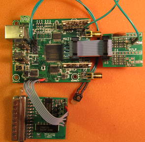
I put together sort of a developer's kit, which should allow the user to quickly see basic functionality. A full-resolution version of this image is available here: mhz100q2_devkit.jpg it's about 3kx3k, 1.1MB.
Contents of the devkit are
The DAC is a simple 8-bit parallel D/A converter using resistors. Signal quality should be adequate for checkout and demos, but it's not intended as a high quality signal source.
The programmer and 6-pin cable are only needed for firmware updates, and should not be
connected for now.
Connect the MHZ100Q2 port P9 to the DAC parallel input using the 10-pin jumper cable, as shown in the figure. Connect the DAC analog output to the MHZ100Q2 input 0 at the 2-pin connector P12 (which is in parallel with the SMA connector). The signal pin is the lower pin, directly in line with the SMA's center pin. The pin above it is ground, and does not need to be connected for this simple demo.
Connect the pushbutton to pins 1 and 3 of P10. Pin 1 is the pin closest to the USB connector. (Pin 2 has 3.3 volts on it, so don't connect to that one by accident).
Test programs are mhz_capture and showit.m.
(You may need to right-click or something on these links to download them). Program
mhz_capture is an executable, compiled for 64-bit Linux, and showit.m
is an Octave program to plot captured data (it should run under Matlab also, but that hasn't been tested yet).
Source code for mhz_capture will be available shortly.
To run it, issue the command
mhz_capture -o/tmp/grab.txt
(no space between the "-o" and the filename.)
The screen output should show a lot of USB info, followed by this, with a new line printed every second or so:
DAC DDS set to 0.01 MHz

Sampling Frequency 5e+06 MHz shift 13

Loop 11:  post 7d0 cic 1 cap 1 wr 755 cmd        2 adc 7f a6 cic fffff00000      fffff zip1 0x1

Loop 21:  post 7d0 cic 1 cap 1 wr 612 cmd        2 adc 7f a6 cic fffff00000      fffff zip1 0x1

Loop 31:  post 7d0 cic 1 cap 1 wr 4d0 cmd        2 adc 7f a6 cic fffff00000      fffff zip1 0x1

Loop 34:  post 7d0 cic 0 cap 2 wr 169 cmd        2 adc 7f a6 cic fffff00000      fffff zip1 0x2
When you press the pushbutton, you should see:
Data written to /tmp/grab.txt

No driver to reattach
and the program should stop. Now, if you do octave -q showit.m, you should see something
like this:
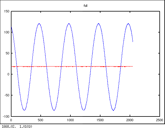
The blue line is channel 0 and the red line is channel 1 (which has no input).
A couple of notes:
mhz_capture --help will show other options you can play with.
Source files for the mhz_capture demo program are available here: mhz100q2_demo.tgz
Partial VHDL source is here:
mhz100q2_part.tgz
These will be removed after I merge them into the Subversion source tree at some point.